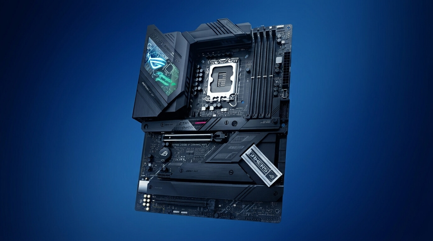
A motherboard is the primary circuit board inside a computer. It connects the CPU, memory, storage drives, expansion cards, and power supply into a single functioning system. Every signal that travels between components passes through pathways etched into the motherboard, making it the physical foundation of desktop and laptop computing.
The motherboard determines which hardware a computer can use. The CPU socket type, memory slot generation, and expansion slot count set fixed limits on compatible processors, RAM modules, and add-in cards. A user cannot install a component that the motherboard does not support, regardless of the component’s individual specifications.
Motherboards vary by size, layout, and feature set. Form factors such as ATX, Micro-ATX, and Mini-ITX define the physical dimensions and the number of components a board can support. Feature differences include the number of memory slots, PCIe slots, USB ports, and onboard headers, which affect the systems a board can build.
This article explains what a motherboard is, how it functions, how form factors differ, and which components make up a typical board, including sockets, chipsets, power delivery, memory and expansion slots, the CMOS battery, ports, headers, standoffs, and diagnostic codes.
What is a computer motherboard?
A computer motherboard is the main printed circuit board that connects and coordinates every major hardware component inside a computer. It links the CPU, RAM, storage devices, graphics card, and power supply through electrical pathways called traces.
The motherboard acts as the physical and electrical backbone of the system. It distributes power from the power supply unit to each connected component and routes data between the CPU and peripheral devices. Manufacturers build motherboards from multiple layers of fiberglass and copper, with copper traces forming the circuits that carry electrical signals across the board.
A motherboard also holds the firmware that starts the computer. This firmware, known as the BIOS or UEFI, runs before the operating system loads and initializes the CPU, memory, and storage controllers. Without a functioning motherboard, individual components cannot communicate, and the computer cannot start.
What is the main function of a motherboard?
The main function of a motherboard is to connect and enable communication between the CPU, memory, storage, and other hardware components so the computer can operate as a single system. It provides the physical sockets, slots, and circuitry that link each component electrically.
The motherboard performs three core functions. It distributes electrical power received from the power supply unit to the CPU, RAM, drives, and expansion cards at the correct voltage for each component. It routes data between components through buses, which are sets of electrical pathways dedicated to specific types of communication, such as the memory bus or the PCIe bus. It also manages system startup through the BIOS or UEFI firmware stored on the board.
The chipset, a set of controller chips fixed to the motherboard, regulates data flow between the CPU and slower components such as storage drives, USB ports, and audio hardware. This regulation prevents faster components from overwhelming slower ones and keeps data transfers synchronized across the system.
What is a motherboard form factor?
A motherboard form factor is a standardized specification that defines a board’s physical dimensions, mounting hole positions, connector placement, and power supply compatibility. The form factor determines which computer cases and power supplies can accommodate the board.
Four form factors are common in consumer desktop computers: E-ATX, ATX, Micro-ATX, and Mini-ITX. E-ATX measures up to 305 x 330 millimetres and provides the most expansion slots and memory slots, suited to high-end workstations. ATX measures 305 x 244 millimetres and offers four memory slots and up to seven expansion slots in most designs. Micro-ATX measures 244 x 244 millimetres, reducing expansion slot count to fit smaller cases. Mini-ITX measures 170 x 170 millimetres and typically includes one expansion slot and two memory slots, designed for compact builds.
A larger form factor generally supports more memory slots, expansion slots, and onboard features, while a smaller form factor reduces case size and cost at the expense of expandability. The form factor also dictates the position of the CPU socket, memory slots, and mounting holes, so a case must match the board’s specification for correct installation.
What are the main parts of a motherboard?
The main parts of a motherboard are the CPU socket, chipset, voltage regulator module (VRM), memory slots, expansion slots, CMOS battery, ports, and headers. Each part performs a distinct role in powering, connecting, or regulating the components attached to the board.
The CPU socket holds and connects the processor to the board’s power and data pathways. The chipset manages communication between the CPU and other components. The VRM converts and regulates power delivered to the CPU. Memory slots hold RAM modules, while expansion slots hold cards such as graphics cards and network adapters. The CMOS battery maintains firmware settings and system time when the computer is powered off. Ports provide external connections for peripherals and displays, and headers provide internal connections for case components such as fans, front-panel buttons, and lighting.
What is a motherboard CPU socket?
A motherboard CPU socket is the physical interface that holds the processor in place and connects it electrically to the motherboard. The socket aligns the CPU’s pins or contact points with the corresponding connections on the board, allowing power and data to pass between the processor and the rest of the system.
Each CPU socket supports a specific range of processor models based on physical pin layout and electrical specification. A CPU must match the socket type of the motherboard; a processor designed for one socket cannot physically install into a different socket type. Socket types differ between manufacturers and processor generations, so a motherboard’s socket determines which CPU generations remain compatible with that board.
The socket also anchors the cooling system. A retention bracket built into or around the socket secures a CPU cooler, ensuring consistent contact between the cooler’s base and the processor for effective heat transfer.
What does LGA socket mean?
LGA stands for Land Grid Array, a CPU socket design in which the pins are located on the motherboard rather than on the processor. The CPU has flat contact points, called lands, that press against spring-loaded pins in the socket when the processor is installed.
Intel processors commonly use LGA sockets, with designations such as LGA 1700 or LGA 1200 indicating the number of pins in the socket. Because the pins remain fixed to the motherboard, a bent pin can be more difficult to repair without professional equipment, though the CPU itself is less exposed to physical pin damage during installation.
What does PGA socket mean?
PGA stands for Pin Grid Array, a CPU socket design in which the pins are located on the underside of the processor rather than on the motherboard. The socket contains matching holes that receive the processor’s pins when installed.
AMD has used PGA sockets in several desktop processor lines, including AM4. Because the pins sit on the CPU, careless handling during installation can bend or damage them, requiring more caution when aligning and seating the processor compared with an LGA design.
What is a chipset on a motherboard?
A chipset on a motherboard is a set of integrated circuits that manages data communication between the CPU and other components, including storage drives, USB ports, and expansion slots. The chipset determines which features and connectivity options a motherboard supports.
Manufacturers design chipsets for specific CPU socket generations, and each chipset model supports a defined combination of features, such as the number of USB ports, SATA connections, PCIe lanes, and overclocking support. A motherboard’s chipset therefore affects performance tuning options, the number of storage drives it can support, and compatibility with certain CPU features.
Chipsets are typically classified by tier. A higher-tier chipset provides more PCIe lanes, additional connectivity, and overclocking support, while a lower-tier chipset offers a reduced feature set suited to standard computing tasks.
What does a chipset do compared to a CPU?
A chipset manages communication and data routing between the CPU and peripheral components, while the CPU performs the computer’s core processing calculations. The CPU executes instructions and processes data, whereas the chipset coordinates how that data reaches storage devices, expansion cards, and ports.
The CPU contains integrated controllers for high-speed components such as RAM and the primary graphics card connection, but the chipset handles lower-speed traffic, including USB, SATA, and additional PCIe lanes. This division of tasks reduces the processing burden on the CPU and allows the motherboard to support a broader range of peripherals.
What does VRM mean on a motherboard?
VRM stands for Voltage Regulator Module, a component on the motherboard that converts and regulates the voltage supplied to the CPU. The VRM steps down the higher voltage delivered by the power supply unit to the lower, precise voltage the processor requires to operate.
A VRM consists of components including MOSFETs, chokes, and capacitors arranged into individual power phases. Each phase handles a portion of the total current delivered to the CPU, and distributing the load across multiple phases reduces heat generation and voltage fluctuation. A VRM with insufficient capacity can cause voltage instability under heavy CPU load, particularly during overclocking or sustained high-performance workloads.
What are motherboard power phases?
Motherboard power phases are individual voltage regulation circuits within the VRM that share the electrical load delivered to the CPU. Each phase contains its own set of MOSFETs, inductors, and capacitors, and operates in coordination with the other phases to supply stable power.
A motherboard with more power phases distributes current across a larger number of circuits, which reduces the heat generated per phase and improves voltage stability under sustained load. Boards intended for high-performance or overclocked CPUs typically include a higher phase count, while boards designed for standard use include fewer phases sufficient for stock CPU power requirements.
What are motherboard memory slots?
Motherboard memory slots are the physical connectors that hold RAM modules and link them to the CPU’s memory controller. Each slot contains electrical contacts that align with the notches on a RAM module, allowing data to transfer between the memory and the rest of the system.
The number of memory slots varies by form factor and model, ranging from two slots on compact boards to four or more slots on full-size ATX and E-ATX boards. Memory slots also correspond to a specific RAM generation, such as DDR4 or DDR5, and a motherboard supports only the RAM generation matching its memory controller and slot design. Installing modules in matched pairs or sets across designated slots enables dual-channel or quad-channel memory operation, which increases data transfer bandwidth compared with using a single module.
How many RAM slots should a motherboard have?
A motherboard should have at least two RAM slots to support dual-channel memory, while four RAM slots provide greater flexibility for future memory upgrades. Two slots suit compact builds with fixed memory requirements, while four slots allow a user to add capacity later without replacing existing modules.
Users building systems for gaming or general productivity commonly select boards with four memory slots, which support up to 128 GB or more of total RAM depending on module capacity. Users prioritizing a smaller case size, such as Mini-ITX builds, typically accept two memory slots as a limitation of the compact form factor.
What are motherboard expansion slots?
Motherboard expansion slots are connectors that allow add-in cards, such as graphics cards, sound cards, and network adapters, to attach to the motherboard and communicate with the CPU. The most common expansion slot standard in current motherboards is PCI Express (PCIe).
PCIe slots come in different physical sizes, including x16, x8, x4, and x1, which indicate the number of data lanes available to the slot. A larger slot size, such as x16, provides more bandwidth and is typically used for graphics cards, while smaller slots such as x1 suit lower-bandwidth cards like network adapters or capture cards. The number and arrangement of expansion slots depend on the motherboard’s form factor and chipset, with larger boards generally offering more slots.
How many PCIe slots should a motherboard have?
A motherboard should have at least one PCIe x16 slot to support a dedicated graphics card, with additional slots needed only for users installing multiple expansion cards. A single x16 slot meets the requirements of most standard desktop builds that use one graphics card and no additional add-in hardware.
Users who require extra expansion, such as a dedicated sound card, capture card, or additional storage controller, need a motherboard with two or more PCIe slots, typically a combination of one x16 slot and one or more smaller x1 or x4 slots. Compact Mini-ITX boards generally include only one PCIe slot due to space constraints.
What is a motherboard CMOS battery?
A motherboard CMOS battery is a small coin-cell battery that powers the CMOS memory chip responsible for storing BIOS or UEFI settings and maintaining the system clock when the computer is unplugged or powered off. CMOS stands for Complementary Metal-Oxide-Semiconductor, the chip technology used to store this configuration data.
The CMOS battery is typically a CR2032 lithium coin cell mounted in a socket on the motherboard. It supplies continuous low-level power to retain settings such as boot order, hardware configuration, and date and time, even when the computer is disconnected from mains power. A CMOS battery generally lasts several years, with a typical service life of two to ten years depending on motherboard design and usage.
Will a motherboard work without a CMOS battery?
A motherboard will start and operate without a CMOS battery, but it will lose stored BIOS settings and reset the system clock each time the power supply is disconnected. The computer resets custom firmware settings to factory defaults, and the date and time revert to a default value on each cold start.
A depleted or missing CMOS battery does not prevent the computer from booting under normal circumstances, provided that no custom BIOS configuration is required for startup. However, systems relying on specific settings, such as a custom boot order or manually configured RAM timings, require these settings to be re-entered after every full power loss when the battery cannot hold them.
What are the different types of computer ports?
The different types of computer ports on a motherboard’s rear I/O panel include USB ports, Ethernet ports, display outputs, and audio jacks, each providing an external connection for a specific category of peripheral device. These ports remain the primary interface between the motherboard and devices outside the case.
USB ports connect peripherals such as keyboards, mice, and external storage. Ethernet ports connect the system to a wired network. Display outputs, including HDMI and DisplayPort, connect a monitor to the motherboard’s integrated graphics when present. Audio jacks connect speakers, headphones, and microphones to the onboard sound controller. The number and combination of these ports vary by motherboard model and price tier.
What USB ports does a motherboard have?
A motherboard typically has a combination of USB-A and USB-C ports, distributed across different USB standards such as USB 2.0, USB 3.2, and, on newer boards, USB4. Each standard provides a different maximum data transfer speed, ranging from 480 megabits per second for USB 2.0 to 40 gigabits per second for USB4.
Rear I/O panels commonly include four to ten USB ports, depending on the chipset and board tier, supplemented by internal USB headers that connect to front-panel case ports. Higher-tier motherboards generally include a greater number of high-speed USB 3.2 or USB4 ports, while budget boards allocate more ports to the slower USB 2.0 standard.
What is a motherboard Ethernet port?
A motherboard Ethernet port is a rear I/O connector, using the RJ45 connector standard, that provides a wired network connection between the computer and a router, switch, or modem. The port connects to an onboard network controller chip that manages data transmission across the network.
Most consumer motherboards include a single Gigabit Ethernet port, supporting data transfer speeds up to 1 gigabit per second, while higher-end boards may include 2.5 Gigabit or 10 Gigabit Ethernet controllers for faster wired networking. A wired Ethernet connection generally provides more stable and lower-latency network performance than Wi-Fi under equivalent network conditions.
What is the DisplayPort on a motherboard?
The DisplayPort on a motherboard is a digital video output connector that transmits video and audio signals from the board’s integrated graphics processor to a monitor. It functions only on motherboards paired with a CPU that includes integrated graphics, since the port has no independent graphics processing capability.
DisplayPort supports high resolutions and refresh rates, including 4K resolution at high refresh rates on supporting hardware, and carries audio alongside video through a single cable. When a dedicated graphics card is installed, the system typically routes video output through the graphics card’s own ports instead of the motherboard’s DisplayPort, though both can remain physically available.
What does a motherboard header do?
A motherboard header is a small set of pins on the board that provides an internal connection point for case components, such as fans, front-panel buttons, LED indicators, and USB connectors. Headers differ from ports in that they connect internally within the case rather than to external peripherals.
Headers transmit power, data, or control signals depending on their type. A fan header supplies power and speed control signals to a case or CPU fan. A front-panel header connects the case’s power button, reset button, and status LEDs to the motherboard. A USB header extends internal USB connectivity to front-panel ports on the case. Motherboard manufacturers label each header, and the labeling typically matches instructions in the motherboard’s manual for correct connection.
What are motherboard front panel headers?
Motherboard front panel headers are pin sets that connect a computer case’s power button, reset button, power LED, and hard drive activity LED to the motherboard. These headers allow the case’s physical buttons and indicator lights to control and reflect the system’s operating state.
Front panel headers are typically grouped together near the bottom edge of the motherboard and follow a standardized pin layout, though exact pin order can vary between manufacturers. Connecting the case’s power switch cable to the correct pins on this header allows the power button to start and shut down the system, while the LED connections display power status and storage activity.
How are motherboard headers and ports different?
Motherboard headers connect internal case components, while ports connect external devices outside the case. A header consists of exposed pins mounted directly on the motherboard’s surface, whereas a port includes a shielded connector accessible from the rear or front of the case.
A header requires a cable to run from an internal component, such as a case fan or front-panel switch, directly to the pins on the board. A port, by contrast, accepts a cable plugged in from outside the case, such as a USB cable connecting an external mouse. Both serve as connection points, but headers operate within the enclosed system while ports interface with the external environment.
What is a fan header on a motherboard?
A fan header on a motherboard is a small connector that supplies power and, in most cases, speed control signals to a case fan or CPU cooler fan. The header allows the motherboard’s firmware or software to regulate fan speed based on system temperature.
Fan headers commonly use a 4-pin design supporting Pulse Width Modulation (PWM), which adjusts fan speed by varying the electrical signal without changing voltage, or a 3-pin design that adjusts speed through voltage control (DC mode). A motherboard typically includes one CPU fan header near the CPU socket and multiple system fan headers distributed across the board for case fans.
What is the RGB header for on a motherboard?
The RGB header on a motherboard supplies power and control signals to addressable or non-addressable RGB lighting components, such as LED strips or fans, allowing software to control their color and lighting effects. The header connects lighting hardware to the motherboard’s onboard lighting controller.
Motherboards typically include two RGB header types: a standard 4-pin 12V RGB header for single-color lighting across an entire strip, and a 3-pin 5V addressable RGB (ARGB) header for individually controllable LEDs capable of displaying multiple colors and patterns simultaneously. The header type must match the connected lighting hardware, since a mismatched voltage connection can damage the lighting component.
What is meant by a motherboard standoff?
A motherboard standoff is a small metal or plastic spacer that raises the motherboard away from the metal surface of the computer case during installation. Standoffs screw into pre-threaded mounting points inside the case and align with corresponding mounting holes on the motherboard.
Standoffs prevent the underside of the motherboard, which contains exposed electrical traces and solder points, from directly contacting the case’s metal chassis. Direct contact between the board and the case can create an electrical short circuit, potentially damaging the motherboard or connected components. Correct standoff placement matches the mounting hole pattern defined by the motherboard’s form factor, ensuring the board sits level and secured within the case.
What are motherboard beep codes?
Motherboard beep codes are a series of audible tones emitted through a small onboard speaker during startup, used to indicate the status or failure point of the system before video output becomes available. Each beep pattern corresponds to a specific hardware condition defined by the motherboard’s BIOS manufacturer.
A single short beep commonly indicates a successful startup with no detected errors, while patterns of repeated or combined long and short beeps typically indicate specific faults, such as missing memory, a failed graphics card connection, or a CPU initialization error. Beep code patterns differ between BIOS manufacturers, such as AMI, Award, and Phoenix, so identifying the correct fault requires matching the beep pattern to the specific motherboard or BIOS documentation.
What are POST codes on a motherboard?
POST codes on a motherboard are numeric or alphanumeric values displayed during the Power-On Self-Test (POST) process, indicating the specific stage of hardware initialization the system has reached or where it has failed. Many motherboards display these codes on a small built-in LED display or through a set of debug LEDs.
The POST process checks core components, including the CPU, memory, and graphics output, in a defined sequence before handing control to the operating system. A POST code that stops changing or remains fixed at a specific value indicates a failure at that stage, allowing a technician to narrow a hardware fault to a specific component rather than testing the entire system. Motherboard manufacturers publish POST code reference tables in their documentation to translate each code into its corresponding diagnostic meaning.
How do you choose a motherboard for gaming?
Choosing a motherboard for gaming requires matching the board’s CPU socket, chipset, and form factor to the selected processor and case, then confirming sufficient VRM capacity, memory support, and expansion slots for the intended graphics card and storage configuration. The graphics card and CPU generally have a greater direct impact on gaming performance than the motherboard itself, so the board’s primary role is ensuring compatibility and stability rather than increasing frame rates.
The CPU socket must match the chosen processor exactly, since a mismatched socket prevents installation regardless of other specifications. The chipset should support the desired features, such as overclocking on unlocked CPUs or a sufficient number of PCIe lanes for the graphics card and NVMe storage drives. VRM quality affects power stability under sustained gaming loads, particularly for higher-power CPUs or overclocked configurations, making phase count and cooling relevant for demanding builds.
Memory slot count and supported RAM speed affect how much RAM a system can hold and how fast it operates, both of which influence performance in memory-sensitive games. Expansion slot layout should accommodate the graphics card and any additional cards, such as a Wi-Fi adapter or capture card, without blocking airflow or adjacent slots. Form factor should match the target case size, balancing available features against the physical space required for the build.
High-performance gaming PCs built for gamers, creators, and competitors.
More From The Journal
How to Choose a Motherboard: A Complete Buying Guide
Learn how to choose a motherboard by comparing socket compatibility, chipset features, RAM support, PCIe slots, storage options, rear I/O, and power delivery.
What Is a CPU Socket?
Understand what a CPU socket is, how it connects a processor to the motherboard, the difference between LGA and PGA, and why socket compatibility matters.