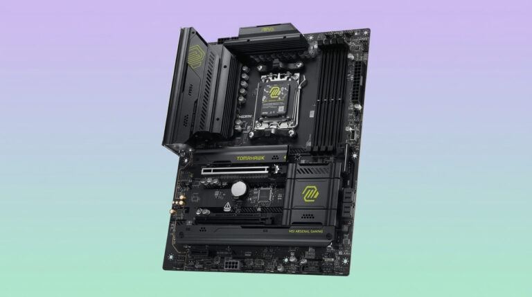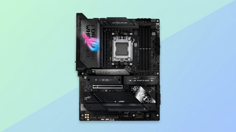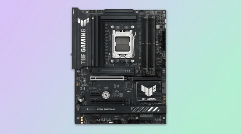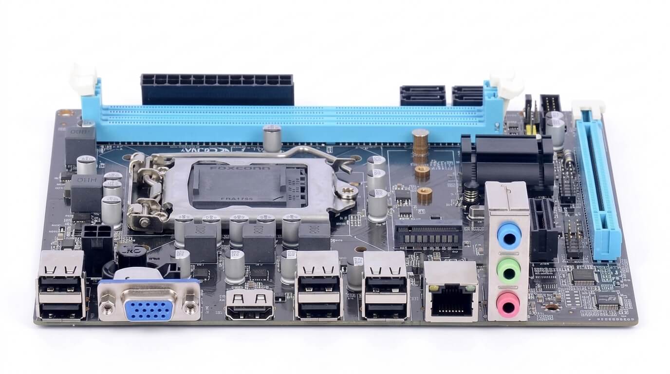
A motherboard connects every core component of a computer, and it does this through a defined set of ports and connectors on its rear panel, its surface, and its internal headers. These ports allow the central processing unit, memory, storage drives, graphics output, and peripheral devices to exchange data and receive power through a single circuit board.
Motherboard ports fall into several functional categories, including data ports for peripherals, display outputs for monitors, storage connectors for drives, power connectors for the system’s power supply, and internal headers for case-mounted components. Each category serves a distinct function, and the number and mix of ports present on a board depends on its form factor, chipset, and intended market segment.
Modern motherboards combine current-generation ports, such as USB-C and M.2 slots, with legacy ports that remain in limited use for compatibility with older hardware. Understanding this port layout helps a buyer match a motherboard to existing peripherals, plan future upgrades, and avoid compatibility issues during a build.
This article explains what a motherboard port is, how many ports a typical board includes, the main port categories and their functions, legacy ports still found on some boards, how to read a motherboard ports diagram, how to identify the ports on a specific board, and how to select a motherboard based on port requirements.
What Is a Motherboard Port?
A motherboard port is a physical connection point on the motherboard that allows a cable, drive, or expansion device to transmit data, video, or power to and from the system. Each port follows a defined electrical and physical standard, which determines the type of connector it accepts and the data or power it can carry.
Motherboard ports are located in two main areas: the rear I/O panel and the surface or edges of the board. The rear I/O panel groups external-facing ports, such as USB and display outputs, into a single cluster accessible from outside the case. The board surface holds internal connectors, such as SATA ports, M.2 slots, and header pins, which link to drives and case-mounted components inside the chassis.
A port differs from a slot in physical form but serves a related purpose: both provide a defined interface between the motherboard’s circuitry and an external or internal device. Port type, connector shape, and signaling standard together determine which devices a given port supports.
How Many Ports Does a Motherboard Have?
A motherboard typically includes between 4 and 12 rear I/O ports, along with 2 to 8 internal SATA connectors, 1 to 5 M.2 slots, and several internal headers for front-panel and fan connections. The exact number varies by motherboard model, chipset, and form factor.
Entry-level motherboards generally include a smaller rear I/O cluster and fewer M.2 slots, while high-end motherboards expand the port count through additional USB-C connectors, multiple M.2 slots, and extra SATA connectors. Chipset capability sets the upper limit on how many high-speed ports a board can support, and manufacturers then allocate that capacity across USB, storage, and networking ports according to the board’s target price and use case.
What Determines the Number of Ports on a Motherboard
The chipset, form factor, and price tier of a motherboard determine its total port count. The chipset defines the maximum number of USB, SATA, and PCIe lanes available, which limits how many ports the manufacturer can implement.
Form factor affects available physical space: a larger board provides more surface area for headers, slots, and connectors than a smaller board. Price tier affects component selection, since manufacturers reserve additional USB-C ports, extra M.2 slots, and expanded SATA connectivity for mid-range and premium boards rather than entry-level models. CPU generation also plays a role, because newer processors can supply their own PCIe lanes directly to certain M.2 slots, which increases the total storage connectivity a board can offer without relying solely on the chipset.
Typical Port Count by Motherboard Size (ATX vs. Micro-ATX vs. Mini-ITX)
ATX motherboards typically include 6 to 10 rear USB ports, 4 to 8 SATA connectors, and 2 to 5 M.2 slots. Micro-ATX motherboards typically include 4 to 8 rear USB ports, 4 to 6 SATA connectors, and 1 to 3 M.2 slots. Mini-ITX motherboards typically include 4 to 8 rear USB ports, 2 to 4 SATA connectors, and 1 to 2 M.2 slots.
| Form factor | Rear USB ports | SATA connectors | M.2 slots |
|---|---|---|---|
| ATX | 6–10 | 4–8 | 2–5 |
| Micro-ATX | 4–8 | 4–6 | 1–3 |
| Mini-ITX | 4–8 | 2–4 | 1–2 |
The larger surface area of an ATX board allows manufacturers to fit more internal headers and expansion slots, which increases the practical ceiling for SATA and M.2 connectivity. Mini-ITX boards limit internal connectivity because of their reduced physical footprint, even when paired with a high-end chipset, while rear I/O port counts across ATX and Mini-ITX boards can be similar since the rear panel dimensions do not scale directly with the board’s overall size.
Types of Motherboard Ports and Connectors
A motherboard includes seven main categories of ports and connectors: USB ports, display ports, networking ports, audio ports, storage connectors, power connectors, and internal headers. Each category connects a distinct class of device or component to the motherboard’s circuitry.
USB and display ports sit on the rear I/O panel and connect external peripherals and monitors. Networking and audio ports also sit on the rear panel and handle wired network access and sound input or output. Storage connectors and power connectors sit on the board surface and link drives and the power supply unit directly to the board. Internal headers sit along the board’s edges and connect case-mounted components such as front-panel buttons, case fans, and additional USB ports on the case itself.
USB Ports (USB-A, USB-C, USB 2.0/3.x)
USB ports on a motherboard connect external peripherals, such as keyboards, mice, external drives, and hubs, using either the USB-A or USB-C connector shape. USB-A uses a rectangular connector and supports only one insertion orientation, while USB-C uses a smaller, reversible oval connector.
The USB generation determines transfer speed and, for USB-C, additional capability. USB 2.0 supports a maximum data rate of 480 megabits per second. USB 3.2 Gen 1 supports up to 5 gigabits per second, USB 3.2 Gen 2 supports up to 10 gigabits per second, and USB 3.2 Gen 2×2 supports up to 20 gigabits per second on compatible USB-C ports. Some motherboards also include USB4 ports, which support data rates up to 40 gigabits per second and can carry DisplayPort video signals over the same connector.
USB-C ports on higher-end motherboards often support Power Delivery, which allows the port to charge connected devices at higher wattages than a standard USB-A port. A motherboard’s rear panel typically mixes USB-A and USB-C ports across different USB generations to balance peripheral compatibility with high-speed device support.
Display Ports (HDMI, DisplayPort, DVI, VGA)
Display ports on a motherboard connect the board’s integrated graphics output to a monitor, and they function only when the installed CPU includes integrated graphics. HDMI and DisplayPort are the two display connectors found on current motherboards, while DVI and VGA appear mainly on older or budget boards.
HDMI transmits both video and audio over a single cable and supports resolutions up to 4K at 60 hertz on HDMI 2.0 or up to 4K at 120 hertz and 8K at 60 hertz on HDMI 2.1, depending on the port’s specification. DisplayPort transmits video and audio in the same way as HDMI and supports comparable or higher resolutions and refresh rates depending on the DisplayPort version implemented on the board. DVI transmits video only, without audio, and supports a maximum resolution lower than HDMI or DisplayPort. VGA transmits an analog video signal, produces lower image sharpness than digital connectors, and appears only on older or entry-level boards for compatibility with legacy displays.
A motherboard with a discrete graphics card installed does not use its onboard display ports for video output, since the graphics card supplies its own display connectors instead.
Networking Ports (Ethernet/LAN)
The networking port on a motherboard is an Ethernet (LAN) port that connects the system to a wired network using an RJ45 connector. This port links the board’s onboard network controller to a router, switch, or modem through a standard Ethernet cable.
Common Ethernet speeds on motherboards include Gigabit Ethernet, which supports up to 1 gigabit per second, and 2.5 Gigabit Ethernet, which supports up to 2.5 gigabits per second. Some higher-end motherboards include 5 Gigabit or 10 Gigabit Ethernet ports for faster wired network throughput. Most motherboards include a single Ethernet port, though server-oriented and workstation boards often include two or more Ethernet ports for network redundancy or link aggregation.
Audio Ports
Audio ports on a motherboard connect speakers, headphones, and microphones to the board’s onboard audio codec. A standard rear audio cluster includes color-coded 3.5mm jacks for line-out, microphone input, and line-in, along with an optical S/PDIF port on some boards for digital audio output to external receivers.
The number of audio jacks ranges from three on entry-level boards to six or more on boards designed for multi-channel surround sound output. The onboard audio codec’s specification determines the maximum supported sample rate and bit depth, which affects overall audio fidelity independent of the jack count.
Storage Connectors (SATA, M.2/NVMe)
Storage connectors link internal drives to the motherboard, and the two main types are SATA ports and M.2 slots. SATA ports use a flat, L-shaped connector and support a maximum data transfer rate of 6 gigabits per second under the SATA III standard, which is the version used on current motherboards.
M.2 slots accept compact M.2 drives directly onto the board surface without a separate data cable. An M.2 slot wired for NVMe over PCIe supports significantly higher transfer speeds than SATA, with PCIe 3.0 M.2 slots reaching up to 32 gigabits per second and PCIe 4.0 M.2 slots reaching up to 64 gigabits per second, depending on the number of PCIe lanes assigned to the slot. Some M.2 slots support SATA-based M.2 drives instead of NVMe drives, so the slot’s supported protocol must match the installed drive for the connection to function.
Power Connectors (24-pin, CPU 8-pin)
Power connectors deliver electricity from the power supply unit to the motherboard and its components. The primary connector is a 24-pin connector that supplies power to the board itself, including the chipset, memory slots, and expansion slots.
A separate CPU power connector, most commonly an 8-pin connector, supplies dedicated power to the processor. Some high-power boards include a second 4-pin or 8-pin CPU connector alongside the primary 8-pin connector to support processors with higher power requirements. Additional power connectors, such as 6-pin or 8-pin PCIe power inputs on the board itself, appear on select high-end motherboards to provide extra power to PCIe expansion slots.
Internal Headers (front panel, fan, USB headers)
Internal headers are pin-based connectors on the motherboard surface that link case-mounted components to the board. Front-panel headers connect the case’s power button, reset button, power LED, and drive activity LED to the motherboard’s control circuitry.
Fan headers supply power and speed control to case fans and CPU coolers, and most motherboards include four to eight fan headers distributed across the board. USB headers connect additional USB ports mounted on the front or top of a case to the motherboard’s internal USB controller, and these headers come in standards matching USB 2.0, USB 3.x, or USB-C, depending on the header’s pin configuration.
Legacy Ports Still Found on Some Motherboards
Legacy ports are connector types developed for earlier computing standards that remain present on some current motherboards for backward compatibility with older peripherals and equipment. Manufacturers typically include legacy ports on business, industrial, or budget-oriented boards rather than on mainstream consumer boards.
VGA Port
A VGA port is an analog display connector that transmits video signals to a monitor using a 15-pin, trapezoid-shaped connector. VGA produces lower maximum resolution and image sharpness than digital display connectors such as HDMI or DisplayPort, since the analog signal is more susceptible to interference over cable length.
VGA remains present on some office and budget motherboards to support older monitors, projectors, and KVM switches that lack digital video inputs.
COM (Serial) Port
A COM port, also called a serial port, is a 9-pin connector that transmits data one bit at a time over a single communication channel. COM ports support a maximum data rate far lower than USB, typically up to 115.2 kilobits per second in standard configurations.
COM ports remain present on industrial, point-of-sale, and business motherboards to support legacy equipment such as barcode scanners, receipt printers, and programmable industrial controllers that rely on serial communication.
PS/2 Port
A PS/2 port is a round, 6-pin connector originally used to connect keyboards and mice to a computer. A motherboard with PS/2 support typically includes one or two PS/2 ports, distinguished by color coding for keyboard and mouse connections.
PS/2 ports remain present on some motherboards because they allow keyboard input to function during the earliest stage of system boot without relying on USB initialization, which benefits users who need reliable access to BIOS settings or troubleshooting tools before the operating system loads.
Motherboard Ports Diagram
A motherboard ports diagram is a labeled illustration that identifies the location and function of each port and connector on the board, typically divided into the rear I/O panel and the internal board surface. The rear I/O panel section of the diagram labels USB ports, display outputs, the Ethernet port, and audio jacks in the order they appear on the physical cluster.
The internal board section of the diagram labels the 24-pin power connector, CPU power connector, SATA ports, M.2 slots, and headers for the front panel, fans, and internal USB connections. Motherboard manufacturers publish this diagram in the product manual, and it typically uses numbered callouts or labeled boxes that correspond to a legend describing each connector’s function and supported standard.
Referring to the manufacturer’s specific diagram for a given board model provides the most accurate reference, since port placement and quantity vary between models even within the same product line.
How to Identify the Ports on Your Own Motherboard
To identify the ports on a specific motherboard, locate the model name printed on the board itself, then check the rear I/O panel and internal connectors against the manufacturer’s official documentation. The model name typically appears silkscreened near the CPU socket or along one edge of the board.
Cross-reference the printed model name with the manufacturer’s product page or user manual, which lists the exact port count, port type, and port location for that model. For ports without visible labels, check for small printed markings near each connector, such as “SATA1,” “USB2,” or “CPU_FAN,” which correspond to the labels used in the manual’s diagram. When the physical board is not accessible, system information utilities built into the operating system, or third-party hardware identification tools, can report the motherboard model, which can then be matched to the correct manual.
Choosing a Motherboard With the Most Ports
Choosing a motherboard with the most ports requires matching the board’s USB, storage, and expansion connectivity to the number and type of devices the system needs to support. A build with multiple storage drives requires a board with enough SATA ports and M.2 slots to accommodate each drive, while a build with several USB peripherals requires a sufficient mix of USB-A and USB-C ports on the rear I/O panel.
Higher-tier motherboards within the same chipset generation generally offer more rear USB ports, additional M.2 slots, and extra internal headers compared with entry-level boards using the same chipset. Confirming the exact port count and type against the manufacturer’s specification sheet, rather than relying on the board’s marketing tier alone, verifies that the selected model meets the system’s connectivity requirements before purchase.