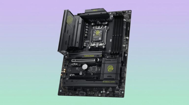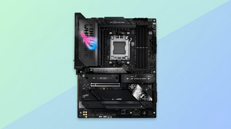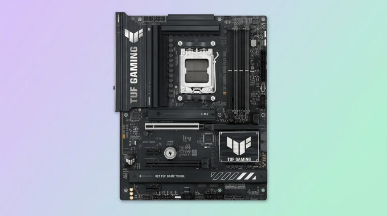
A motherboard contains dozens of small pin groups beyond its major slots and sockets. These pin groups connect the case switches, status LEDs, fans, front-panel ports, and internal modules to the board’s circuitry. Builders who skip or misread them risk a system that powers on but shows no LED activity, front USB ports that stay dead, or fans that never spin under load.
Each pin group follows a standardized layout and a printed label silkscreened next to it, such as F_PANEL, USB1, or JAUDIO1. The label identifies the header’s function and, in most cases, its pin count and voltage. Matching the correct cable to the correct header, in the correct orientation, is a required step in every custom PC build and in most component upgrades.
This article groups motherboard headers into six functional categories: front panel controls, fan connectors, USB front-panel connectors, audio connectors, RGB and ARGB lighting connectors, and a set of less common headers that appear on specific board models. Each section explains what the header connects, its typical pin configuration, and how to identify it on a board.
The information applies to desktop motherboards from current chipset generations across ATX, Micro-ATX, and Mini-ITX form factors. Exact header placement varies by manufacturer and model, so the printed circuit board silkscreen and the motherboard manual remain the definitive reference for any specific board.
What Are Motherboard Headers?
A motherboard header is a set of exposed pins on the printed circuit board that accepts a cable connector from a case component or internal module. Headers differ from slots and sockets in that they carry low-voltage signal or power connections through a small pin block rather than a full-size port.
Each header serves one defined function, such as reading a switch input, sending power to a fan, or carrying an audio signal. A header contains between two and twenty pins, arranged in one or two rows, and most include a printed identifier on the board and in the motherboard manual. Many headers also include a notch, a missing pin, or a keyed shroud that prevents the cable from being inserted in the wrong orientation.
Headers sit at fixed locations on the board, typically along the bottom edge, the right edge near the SATA ports, or close to the CPU socket for fan and pump connections. A single motherboard includes headers for front-panel switches and LEDs, case and CPU fans, front USB ports, front audio jacks, RGB or ARGB lighting, and additional functions such as TPM or Clear CMOS, depending on the model.
Front Panel Headers: Power, Reset, and Case LEDs
Front panel headers connect the case’s power button, reset button, and status LEDs to the motherboard. The group is usually labeled F_PANEL, JFP1, or Front Panel and sits along the bottom edge of the board.
The header combines several 2-pin connections into one pin block, typically nine or ten pins across two rows. Each pin pair controls one function: the power switch, the reset switch, the power LED, and the hard drive activity LED. Case manufacturers supply individual 2-pin plugs for each function, and some cases combine them into a single connector block that matches common motherboard layouts. Because the pin order is not standardized across all board brands, the motherboard manual specifies which pin pair maps to which function.
Polarity matters for the LED connections but not for the switch connections. A power LED or HDD LED wired in reverse polarity will not light, while a power or reset switch functions correctly in either orientation because it closes a simple circuit rather than passing directional current.
Power Switch Header
The power switch header is the 2-pin connection that turns the system on and off when the case’s power button is pressed. Pressing the button briefly closes the circuit between the two pins, which signals the motherboard to start or stop the power sequence.
The header is part of the F_PANEL block and is commonly labeled PWR_SW, PW_BTN, or PWRBTN. It carries no continuous current; it only detects a momentary short between its two pins, so the connecting wire does not require a specific polarity. A user can start the system without a case button by briefly touching a flathead screwdriver across the two pins, which is a standard troubleshooting method for confirming the motherboard and power supply function correctly.
Reset Switch Header
The reset switch header is the 2-pin connection that restarts the system immediately when the case’s reset button is pressed, without going through a normal shutdown sequence. Closing the circuit between its two pins sends a hard-reset signal to the motherboard.
The header is labeled RESET, RESET_SW, or RST_BTN and sits within the F_PANEL block alongside the power switch header. Like the power switch header, it accepts either wire orientation because it functions as a momentary switch rather than a polarized power connection. Many current cases omit a physical reset button, so this header goes unused on those builds; the motherboard operates normally without a cable connected to it.
Power LED and HDD LED Headers
The power LED header lights an indicator on the case when the system is powered on, and the HDD LED header lights an indicator each time the storage drive receives a read or write request. Both headers are 2-pin connections within the F_PANEL block, typically labeled PLED (or PWR_LED) and HDD_LED.
Unlike the switch headers, both LED headers are polarity-sensitive. The positive pin, marked with a plus sign or a lighter wire color on the case cable, must align with the positive pin on the motherboard header for the LED to illuminate. A reversed connection does not damage the board; it results in an LED that stays off. Some boards combine the power LED into a single 3-pin connector to support both 2-pin and 3-pin case cables, in which case only two of the three pins carry an active signal.
Fan Headers: CPU_FAN, SYS_FAN, CHA_FAN, and AIO_PUMP
Fan headers supply power to case and CPU fans and, on most current boards, allow the motherboard to control fan speed automatically based on temperature. Common labels include CPU_FAN, SYS_FAN, CHA_FAN, and AIO_PUMP, and a board typically includes between two and eight of them depending on its size and target market.
Each header outputs 12V and supports fans up to a defined current limit, commonly 1A to 2A per header. The CPU_FAN header is monitored directly by the motherboard for fan-failure protection: if the board detects no CPU fan signal at startup, it can halt the boot process or trigger a warning to prevent the processor from running without active cooling. SYS_FAN and CHA_FAN headers power auxiliary case fans and are usually adjustable through the BIOS or motherboard software, either by fixed percentage or by a temperature-based curve. AIO_PUMP is a dedicated header for the pump on an all-in-one liquid cooler; it is typically set to run at a fixed high speed rather than a temperature curve, since the pump must circulate coolant continuously regardless of load.
3-Pin vs 4-Pin Fan Headers
A 3-pin fan header supplies power and reports fan speed through voltage control, while a 4-pin fan header adds a dedicated PWM signal wire that controls speed through pulse-width modulation. Both header types are physically compatible with each other; a 3-pin fan connects to a 4-pin header, and a 4-pin fan connects to a 3-pin header, using the shared portion of the pin block.
The difference affects how speed control operates. A 3-pin (DC) header varies the fan’s voltage to change its speed, which produces a narrower control range and can stop some fans below a minimum voltage threshold. A 4-pin (PWM) header keeps a constant 12V supply and instead sends a rapid on/off signal on the fourth pin, letting the fan’s internal controller set the speed based on the pulse ratio. PWM control generally produces finer speed adjustment and a wider range, including near-silent low-speed operation, compared with DC control on the same fan. When a 4-pin PWM fan connects to a 3-pin DC header, the motherboard falls back to voltage-based control and the PWM signal wire remains unused.
CPU_FAN vs CPU_OPT vs AIO_PUMP
CPU_FAN is the primary header for the CPU air cooler or the first fan on a liquid cooler radiator, CPU_OPT (CPU Optional) is a secondary header typically used for a second radiator fan or a supporting case fan, and AIO_PUMP is a dedicated header for a liquid cooler’s pump. All three sit near the CPU socket, since fan and pump cables from CPU coolers need to reach that area without extension cables.
CPU_FAN carries the boot-time fan-failure check described in the fan header overview, so the primary CPU cooling fan should connect there rather than to CPU_OPT. CPU_OPT mirrors CPU_FAN’s power and PWM behavior on most boards but does not always trigger the same failure warning, making it suitable for a secondary fan whose failure should not halt startup. AIO_PUMP differs from both by defaulting to a fixed high-speed profile in the motherboard BIOS, since a liquid cooler pump requires continuous full-speed operation rather than temperature-based throttling; some boards allow AIO_PUMP to be reconfigured in BIOS as a standard fan header if the case uses it for a fan instead of a pump.
USB Headers: USB 2.0, USB 3.0, and USB-C Front Panel Connectors
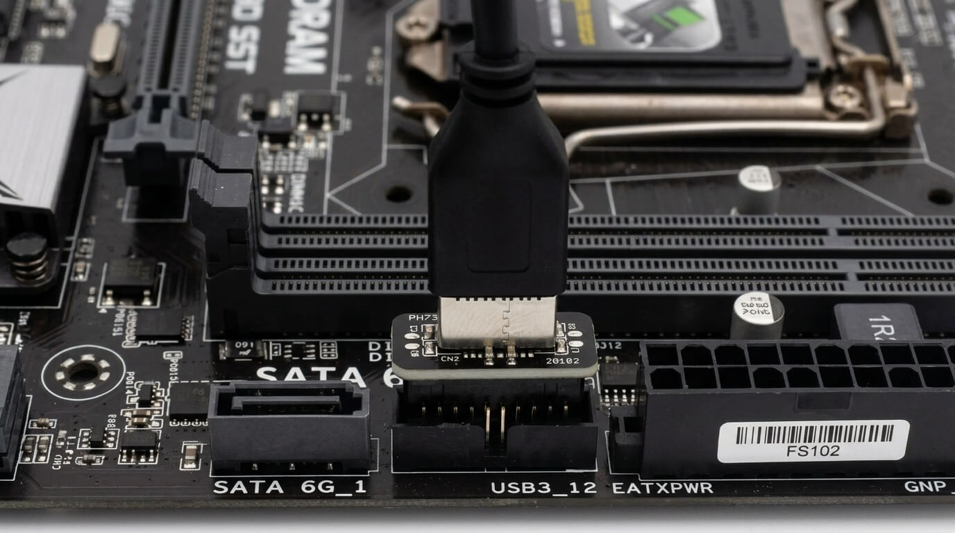
USB headers connect the case’s front or top-panel USB ports to the motherboard, extending USB connectivity from the rear I/O panel to a location the user can reach without turning the case around. A motherboard typically includes one or two USB 2.0 headers, one USB 3.0/3.2 Gen 1 header, and, on many current boards, one USB-C header.
Each header type uses a different pin count and physical shape, and a case’s front-panel USB cable is built to match one specific header type. USB 2.0 and USB 3.0 headers use a rectangular pin block with a keyed notch that prevents reversed insertion, while the USB-C header uses a distinct connector shape unique to that standard. Connecting a case’s front-panel cable to the wrong header type is not physically possible for most combinations, since the pin counts and keying differ between them.
USB 2.0 Header
The USB 2.0 header is a 9-pin (or 10-pin with one pin removed) connector that supplies two USB 2.0 ports, running at a maximum data transfer rate of 480 Mbps per port. It is commonly labeled USB1, USB2, or F_USB1 and sits along the bottom edge of the motherboard.
The nine active pins carry power, ground, and two differential data pairs for each of the two ports, plus a shared ground pin. The header includes a blocked or missing pin position, corresponding to a plugged hole on the case cable connector, which prevents the cable from being inserted upside down. This header type supports front-panel USB ports, internal card readers, and some case-mounted USB hubs.
USB 3.0 / USB 3.2 Gen 1 Header
The USB 3.0 (USB 3.2 Gen 1) header is a 19-pin or 20-pin connector that supplies two USB 3.0 ports, running at a maximum data transfer rate of 5 Gbps per port. It is commonly labeled USB3_1, USB3_2, or F_USB3 and is physically larger than the USB 2.0 header because it carries additional high-speed data pairs.
The extra pins over USB 2.0 support the additional SuperSpeed data lines each USB 3.0 port requires alongside the standard USB 2.0-compatible lines, allowing each port to fall back to USB 2.0 speeds if a USB 2.0 device is connected. The header is keyed with an L-shaped block that fits only one way, preventing a reversed connection. A front-panel USB 3.0 cable is thicker and less flexible than a USB 2.0 cable due to the added shielded pairs, which matters when routing cables in a compact case.
USB-C Front Panel Header
The USB-C front panel header is a dedicated connector, distinct from the USB 2.0 and USB 3.0 pin blocks, that supplies one front or top-panel USB-C port supporting USB 3.2 Gen 2 speeds up to 10 Gbps. It is commonly labeled USB3.2_C1, USB_C, or Type-C Header.
The connector uses a key-shaped, non-rectangular pin arrangement specific to USB-C signaling, which differs from both older USB header types and cannot accept a USB 2.0 or USB 3.0 front-panel cable. Not every motherboard includes this header; its presence depends on the board’s chipset and price tier, and a case with a front-panel USB-C port requires a motherboard with a matching header to use that port. Some boards place the USB-C header near the rear I/O area rather than the bottom edge, so cable length from the case becomes a factor in some builds.
Audio Headers: HD_AUDIO for Front Headphone and Mic Ports
The HD_AUDIO header is a 9-pin connector that carries the analog audio signals for a case’s front-panel headphone and microphone jacks, following the Intel High Definition Audio (HDA) standard used on virtually all current motherboards. It is labeled HD_AUDIO, F_AUDIO, or AAFP and typically sits near the bottom-front edge of the board, close to the front-panel switch header.
The nine pins carry a shared ground, a headphone-out signal pair, a microphone-in signal pair, a jack-detection line, and a sense pin used by the audio codec to identify whether a device is connected to the front port. The header includes one removed pin position that keys the connector to a single correct orientation. Older cases built for the legacy AC’97 audio standard use a different, incompatible pin assignment on the same physical connector shape; connecting an AC’97 cable to an HD Audio header produces distorted sound or silence, and most current motherboards include a BIOS or jumper setting to switch header behavior between the two standards if needed.
RGB and ARGB Headers: 12V RGB vs 5V ARGB
RGB headers and ARGB headers both power lighting components on fans, strips, and coolers, but they differ in voltage, pin count, and control method. A 12V RGB header uses four pins and lights all connected LEDs in a single, uniform color at once, while a 5V ARGB header uses three pins and controls each LED individually, enabling per-LED color patterns and effects.
The 12V RGB header, commonly labeled RGB_LED1 or JRGB1, carries a constant 12V line plus three color channels (red, green, blue) that the motherboard software mixes to set one color across the entire connected strip. The 5V ARGB header, commonly labeled ARGB_LED1 or JRAINBOW1, carries a 5V line, a ground, and a single data line that sends addressing information to each LED chip in sequence, allowing chase effects, rainbow gradients, and independent zone control that a 12V RGB header cannot produce.
The two header types are not interchangeable. Connecting a 5V ARGB device to a 12V RGB header, or the reverse, applies the wrong voltage to the LED controller and can permanently damage the connected component. Most current headers include a keyed shroud and a printed voltage label next to the pins specifically to prevent this mismatch, and manufacturers color-code cables (commonly white connectors for ARGB and black for RGB) to add a second visual check before connecting a device.
Other Motherboard Headers You May See
Beyond the front-panel, fan, USB, audio, and lighting headers found on nearly every board, some motherboards include additional headers tied to specific features, security functions, or troubleshooting tools. Their presence depends on the board’s chipset, target market, and manufacturer, so not every header in this section appears on every model.
TPM Header
The TPM header is a connector that accepts a plug-in Trusted Platform Module card, which stores encryption keys and supports hardware-based security features such as full-disk encryption and Windows 11’s TPM 2.0 requirement. It is labeled TPM or TPM_HDR and typically uses a 14-pin, 17-pin, 19-pin, or 20-pin layout depending on the motherboard manufacturer, with no single pin count standardized across brands.
Many current boards include TPM functionality built into the chipset firmware (fTPM on AMD platforms, PTT on Intel platforms) and expose it through a BIOS setting rather than requiring a physical module, which makes the physical TPM header optional on those systems. A discrete TPM module remains relevant for users who need a dedicated hardware security chip separate from the CPU’s firmware-based implementation, or whose board does not support firmware TPM.
Thunderbolt Header
The Thunderbolt header is a connector that carries video and PCIe signal data from the motherboard to a separate add-in Thunderbolt controller card, enabling Thunderbolt ports on boards that do not have a Thunderbolt controller built into the chipset. It is labeled TB_HEADER or JTBT1 and is typically located near the PCIe slots.
The header does not supply Thunderbolt functionality on its own; it passes display output and data signals from the motherboard’s graphics and chipset connections to the add-in card, which then handles the Thunderbolt protocol itself. A motherboard’s manual specifies which add-in Thunderbolt cards are compatible with its header, since pin layouts and supported bandwidth vary between motherboard generations and are not universally interchangeable.
Speaker or Buzzer Header
The speaker or buzzer header connects a small onboard speaker that emits beep codes during the Power-On Self-Test (POST) sequence, letting a user diagnose hardware problems by counting or interpreting the beep pattern before a display output is available. It is labeled SPEAKER, SPK, or BUZZER and is a 4-pin header, though only two pins are typically active.
Many current motherboards include a built-in piezo speaker soldered directly onto the board, making a separate case speaker cable unnecessary. On boards without a built-in speaker, connecting a case-supplied 4-pin speaker unit to this header restores POST beep diagnostics, which remains useful for troubleshooting when the system produces no video signal and a diagnostic LED display or debug code readout is not present on the board.
Clear CMOS Header
The Clear CMOS header is a 2-pin jumper connection that resets the motherboard’s BIOS settings to factory defaults when briefly shorted, clearing an incorrect overclock, a forgotten BIOS password, or a corrupted configuration that prevents the system from booting. It is labeled CLR_CMOS, CLRTC, or JBAT1 and is typically located near the battery or along the bottom edge of the board.
Shorting the two pins, either with a jumper cap or a metal tool, while the system is powered off and unplugged discharges the CMOS memory that stores BIOS settings, forcing the board to reload its default configuration on the next boot. Some current motherboards replace or supplement this header with a rear-panel Clear CMOS button, which performs the same function without opening the case, but the header remains present on most boards as the standard method.