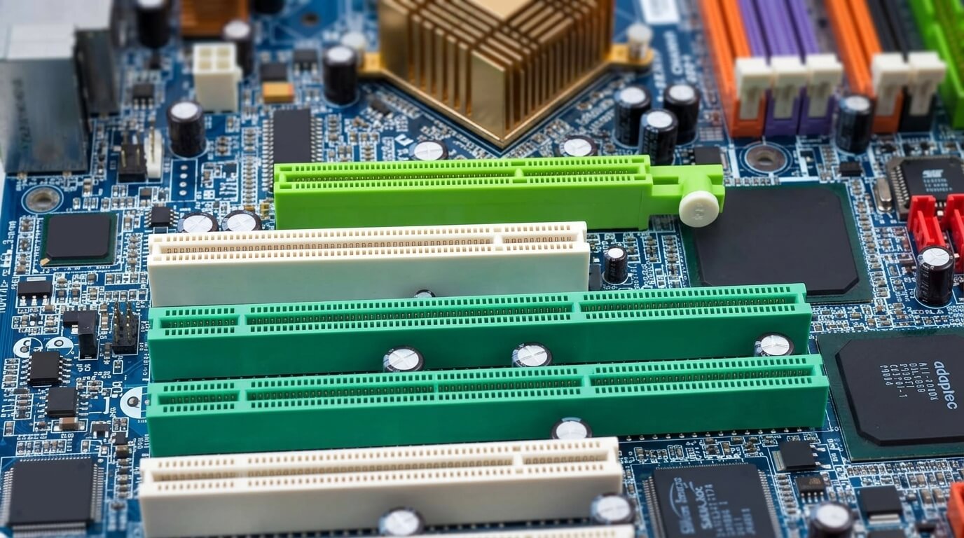
Expansion slots are physical connectors built into a motherboard that let a user add extra hardware components, called expansion cards, to a computer. Each slot links directly to the motherboard’s chipset and processor through a data bus, giving the installed card access to power and to the system’s data pathways. Desktop motherboards typically include multiple expansion slots of different sizes and types, positioned below the CPU socket and memory slots.
The primary function of expansion slots is to extend a computer’s capabilities beyond what is built into the motherboard. A user can install a graphics card to improve video output, a sound card to improve audio processing, or a network card to add wired or wireless connectivity. Without expansion slots, these functions would depend entirely on the components integrated into the motherboard at the time of manufacture.
Expansion slots vary by standard, physical length, and data bandwidth. The two dominant standards in modern computing are PCI (Peripheral Component Interconnect) and PCIe (PCI Express), with PCIe present on virtually all motherboards produced after the mid-2000s. Older standards, including ISA and AGP, appeared in earlier motherboard generations and are largely obsolete in current systems.
This article explains what expansion slots are, where they sit on a motherboard, the slot types and card types a user may encounter, and the factors that affect slot selection and performance.
What Is an Expansion Slot on a Motherboard?
An expansion slot is a socket on a motherboard that accepts an expansion card and connects it to the motherboard’s data bus, power lines, and chipset. The slot provides both an electrical connection and a physical mounting point, holding the card in place while allowing data to move between the card and the rest of the system.
Expansion slots share a common physical design: a narrow connector with multiple metal contacts that align with matching contacts on the edge of an expansion card. The number of contacts, the slot’s physical length, and its supported data-transfer rate depend on the slot standard. A motherboard’s chipset routes data between each expansion slot and the CPU, memory, and storage controllers, allowing an installed card to communicate with the rest of the system.
A motherboard generally includes several expansion slots of different types and sizes, since different cards require different amounts of bandwidth and physical space. A graphics card, for example, uses a larger slot than a network card because it requires substantially more data throughput.
Where Are Expansion Slots Located on a Motherboard?
Expansion slots are located on the lower portion of a motherboard, below the CPU socket and RAM slots, running parallel to the board’s rear edge. This position aligns the slots with the expansion-card openings on the back of a computer case, allowing installed cards to expose their ports (such as video or network connectors) through the case’s rear panel.
The slots run in vertical rows across the width of the motherboard, spaced to prevent adjacent cards from physically interfering with one another. Larger cards, such as graphics cards, occupy the slots closest to the CPU socket because these slots typically carry the highest-bandwidth connection (PCIe x16). Smaller slots for lower-bandwidth cards, such as PCIe x1 slots, are positioned further down the board.
Case design also affects slot accessibility. A computer case includes expansion slot covers on its rear panel that correspond to the motherboard’s slot positions; a user removes these covers to expose the ports of an installed card. The number of usable slots depends on the motherboard’s form factor: a full-size ATX motherboard offers more expansion slots than a compact Micro-ATX or Mini-ITX board.
Types of Expansion Slots on a Motherboard
Motherboards use several expansion slot standards, distinguished primarily by data-transfer method, physical size, and backward compatibility. The two standards found in current systems are PCI and PCIe, while ISA and AGP appear only in older or legacy hardware. Each standard defines its own electrical signaling method, connector shape, and maximum bandwidth, which determines the type and performance of the cards it supports.
Slot type selection depends on the card being installed. A high-bandwidth device, such as a graphics card, requires a PCIe x16 slot, while a lower-bandwidth device, such as a Wi-Fi adapter, operates efficiently in a smaller PCIe x1 slot. The following sections describe each slot type in detail.
PCI Slots (the Legacy Standard)
PCI (Peripheral Component Interconnect) is a parallel expansion slot standard that transfers data over a shared 32-bit or 64-bit bus at a fixed clock speed of 33 MHz or 66 MHz. A PCI slot has a maximum theoretical bandwidth of 133 MB/s on a standard 32-bit, 33 MHz implementation, shared among all devices connected to the same bus.
PCI slots dominated desktop motherboards from the early 1990s through the mid-2000s, supporting cards such as sound cards, modems, and basic network adapters. The shared-bus architecture of PCI limits its performance compared with later standards, since multiple devices on the same bus compete for the same bandwidth. Current motherboards rarely include PCI slots, having replaced them with PCIe, though some specialized or industrial boards retain a single PCI slot for legacy hardware compatibility.
PCIe (PCI Express) Slots - the Modern Standard
PCIe (PCI Express) is a serial expansion slot standard that assigns each connected device its own dedicated data lanes instead of a shared bus, allowing significantly higher and more consistent bandwidth than PCI. Each PCIe lane consists of two pairs of wires, one for sending data and one for receiving data, and multiple lanes combine to form a single slot’s total bandwidth.
PCIe has been the standard expansion interface on desktop and server motherboards since the mid-2000s, replacing PCI and AGP for nearly all card types. A PCIe slot’s bandwidth scales with both its lane count (x1, x4, x8, x16) and its generation (PCIe 1.0 through PCIe 5.0), with each new generation roughly doubling the data rate per lane over its predecessor. This scalability allows PCIe to support devices with widely different bandwidth needs, from low-throughput network cards to high-throughput graphics cards, using the same underlying standard.
PCIe Slot Sizes: x1, x4, x8, and x16
PCIe slots come in four common physical sizes - x1, x4, x8, and x16 - with the number indicating how many data lanes the slot provides. A higher lane count increases the slot’s maximum bandwidth and its physical length on the motherboard.
A PCIe x1 slot provides one lane and suits low-bandwidth cards such as sound cards, USB expansion cards, and basic network adapters. A PCIe x4 slot provides four lanes and commonly supports storage controller cards and some network cards. A PCIe x8 slot provides eight lanes and appears on motherboards with multiple high-bandwidth expansion needs, such as servers or workstations running several storage or networking cards. A PCIe x16 slot provides sixteen lanes, the maximum standard configuration, and is reserved primarily for graphics cards due to their high data-throughput requirements.
Slot size and card size do not always need to match exactly. A shorter card, such as an x1 network card, can be installed in a longer x16 slot, since the connector is backward-compatible; the card simply uses fewer lanes than the slot physically supports.
Older Slot Types You May Still Encounter (ISA and AGP)
ISA (Industry Standard Architecture) and AGP (Accelerated Graphics Port) are older expansion slot standards that have been discontinued on current motherboards but may still appear on legacy or industrial hardware. ISA slots supported early expansion cards, including sound cards and modems, using an 8-bit or 16-bit parallel bus with a maximum bandwidth well below that of PCI.
AGP was a dedicated slot standard created specifically for graphics cards, offering higher bandwidth than PCI for video data before PCIe became available. Manufacturers phased out AGP in favor of PCIe x16 during the mid-2000s, since PCIe offered greater bandwidth and supported a wider range of card types through a single standard. A user working with a computer manufactured before approximately 2005 may still encounter ISA or AGP slots, though replacement cards for these standards are increasingly difficult to find.
PCI vs. PCIe: What’s the Difference?
PCI and PCIe differ primarily in their data-transfer architecture: PCI uses a shared parallel bus, while PCIe uses dedicated serial lanes assigned to each device. This architectural difference gives PCIe substantially higher bandwidth, lower latency, and better scalability than PCI.
On a PCI bus, all connected devices share the same fixed bandwidth, so adding more cards to the bus reduces the data throughput available to each device. On a PCIe connection, each device receives its own dedicated lanes, so one device’s data transfer does not reduce the bandwidth available to another device on a different slot.
PCIe also supports a range of slot sizes (x1 through x16) and multiple generations with increasing per-lane bandwidth, while PCI offers a single fixed bandwidth regardless of the card installed. PCIe additionally supports hot-plugging on certain systems and provides more efficient power delivery to installed cards. These differences are the reason virtually all motherboards produced since the mid-2000s use PCIe rather than PCI as the primary expansion standard.
Types of Expansion Cards You Can Install
Expansion slots accept a range of expansion cards, each designed to add or improve a specific system function. Common categories include graphics cards, sound cards, network and Wi-Fi cards, and capture, RAID, or storage controller cards. Each card type connects through a PCIe slot sized to match its bandwidth requirements.
The card categories differ in the amount of data they need to transfer and the corresponding slot size they require. A graphics card requires the highest bandwidth and uses a PCIe x16 slot, while sound cards, network cards, and most storage controllers operate through smaller PCIe x1 or x4 slots. The following sections describe the primary card categories and their slot requirements.
Graphics Cards (GPU)
A graphics card is an expansion card that processes and outputs video data, typically installed in a motherboard’s PCIe x16 slot to support the high bandwidth required for rendering images, video, and 3D graphics. The card contains its own graphics processing unit (GPU), dedicated video memory, and cooling hardware, operating independently of the motherboard’s integrated graphics, if present.
Graphics cards connect the system to one or more monitors through video outputs such as HDMI or DisplayPort. Gaming systems, video editing workstations, and machine-learning workloads commonly require a dedicated graphics card, since these tasks demand more processing power and memory bandwidth than integrated graphics can provide.
Sound Cards
A sound card is an expansion card that processes audio input and output, typically installed in a PCIe x1 slot due to its comparatively low bandwidth requirement. The card contains a dedicated audio processor and digital-to-analog converter, producing higher audio fidelity and lower latency than a motherboard’s integrated audio chip.
Users who require professional audio recording, high-fidelity playback, or advanced surround-sound processing commonly add a dedicated sound card, since integrated motherboard audio prioritizes general-purpose use over specialized audio performance.
Network and Wi-Fi Cards
A network or Wi-Fi card is an expansion card that adds or upgrades wired or wireless network connectivity, typically installed in a PCIe x1 slot. A wired network card provides an Ethernet port supporting speeds such as 1 Gbps, 2.5 Gbps, or 10 Gbps, depending on the card’s specification. A Wi-Fi card adds wireless connectivity through an integrated antenna or an external antenna connector, supporting current wireless standards such as Wi-Fi 6 or Wi-Fi 6E.
Users install a dedicated network or Wi-Fi card when a motherboard lacks integrated networking, when faster wired speeds are needed, or when a system requires a wireless connection that the motherboard does not natively support.
Capture, RAID, and Storage Controller Cards
A capture card is an expansion card that records or streams video and audio input from an external source, such as a gaming console or camera, and typically requires a PCIe x4 or x8 slot depending on the resolution and frame rate it supports. A RAID or storage controller card manages multiple storage drives, enabling configurations such as RAID 0, RAID 1, or RAID 5 for improved performance or data redundancy, and typically uses a PCIe x4 or x8 slot depending on the number of drives it supports.
These card categories serve users with specific data-handling needs: content creators use capture cards to record or stream external video sources, while users managing large storage arrays or requiring drive redundancy use RAID or storage controller cards to expand a system’s storage capabilities beyond the motherboard’s built-in storage ports.
Do Laptops Have Expansion Slots?
Most laptops do not have traditional PCIe expansion slots, since their compact internal design leaves limited space for full-size card connectors. Laptop manufacturers instead integrate core functions, such as graphics, audio, and networking, directly onto the motherboard or into the processor package.
Some laptops include smaller expansion interfaces, such as M.2 slots, which accept storage drives and, on select models, Wi-Fi or cellular modem cards. These M.2 slots use a physically compact connector and a reduced number of PCIe lanes compared with a desktop PCIe x16 or x4 slot, reflecting the space and power constraints of laptop hardware.
External expansion options exist for laptops that need additional capability beyond integrated or M.2-based components. A Thunderbolt or USB4 port allows a user to connect an external graphics enclosure or other PCIe-based device outside the laptop chassis, providing expansion functionality without requiring an internal PCIe slot.
How to Choose the Right Expansion Slot for Your Card
Choosing the right expansion slot requires matching the card’s physical connector type and lane requirement (x1, x4, x8, or x16) to an available slot on the motherboard that meets or exceeds those requirements. A card with a smaller connector fits and functions in a larger slot of the same standard, but a card with a larger connector does not fit in a smaller slot.
A user should first confirm the card’s required slot size, listed in the card’s technical specifications, before selecting an available motherboard slot. Installing a high-bandwidth card, such as a graphics card, in the motherboard’s primary PCIe x16 slot ensures the card receives its full rated bandwidth, since this slot typically connects directly to the CPU with the maximum available lane count.
Slot placement also affects performance when multiple cards share the motherboard’s total PCIe lanes. Installing a second high-bandwidth card, such as an additional storage controller, in a secondary x16 slot can reduce the primary slot’s available lanes on some motherboards, since the chipset allocates a fixed total number of lanes across all slots. Checking the motherboard manual for lane-allocation details prevents unexpected bandwidth reduction when installing multiple cards simultaneously.
Physical clearance is a further factor in slot selection. A large graphics card can block adjacent slots due to its height and cooling shroud, so a user installing multiple cards should verify that neighboring slots remain accessible before finalizing a configuration.
PCIe Lanes, Generations, and Bandwidth: A Quick Primer
A PCIe lane is a dedicated, bidirectional data pathway between a device and the motherboard’s chipset or CPU, and the number of lanes assigned to a slot directly determines that slot’s maximum data-transfer rate. Each PCIe generation increases the data rate per lane, so the same lane count (such as x16) delivers different total bandwidth depending on the PCIe generation in use.
Each PCIe generation approximately doubles the per-lane bandwidth of its predecessor: PCIe 3.0 delivers roughly 1 GB/s per lane, PCIe 4.0 delivers roughly 2 GB/s per lane, and PCIe 5.0 delivers roughly 4 GB/s per lane. A PCIe 4.0 x16 slot therefore provides roughly double the total bandwidth of a PCIe 3.0 x16 slot, even though both slots use the same sixteen-lane physical size.
PCIe maintains backward and forward compatibility across generations and lane counts, so a PCIe 3.0 card functions in a PCIe 4.0 or 5.0 slot, and a PCIe x8 card functions in a PCIe x16 slot. In these mismatched configurations, the connection operates at the lower of the two specifications: a PCIe 3.0 card in a PCIe 4.0 slot transfers data at the PCIe 3.0 rate, and an x8 card in an x16 slot uses only eight of the available sixteen lanes.
Total motherboard PCIe lane availability depends on the CPU and chipset, since both components contribute a fixed number of lanes that the motherboard distributes across its expansion slots and other components, such as M.2 storage. A system with multiple high-bandwidth cards installed at once may experience reduced per-slot bandwidth if the total available lanes cannot fully supply every populated slot simultaneously.
High-performance gaming PCs built for gamers, creators, and competitors.
More From The Journal
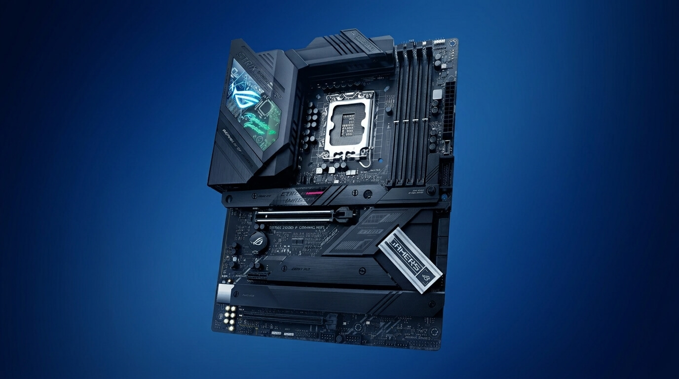
Motherboard: Definition, Function, Sizes, Components
Learn what a motherboard is, what it does, how form factors differ, and which core parts like sockets, chipsets, VRMs, slots, ports, and headers matter most.
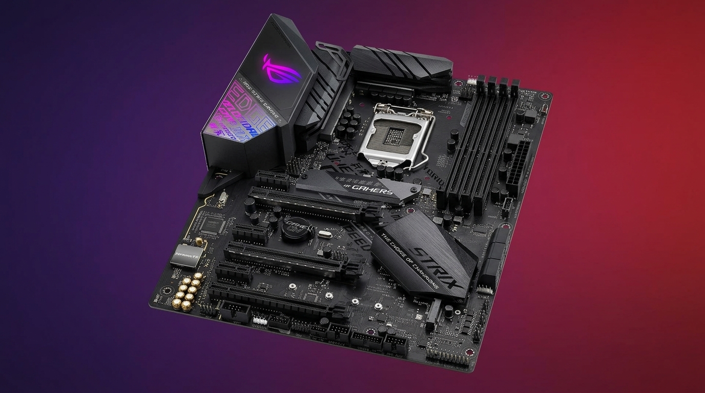
How to Choose a Motherboard: A Complete Buying Guide
Learn how to choose a motherboard by comparing socket compatibility, chipset features, RAM support, PCIe slots, storage options, rear I/O, and power delivery.