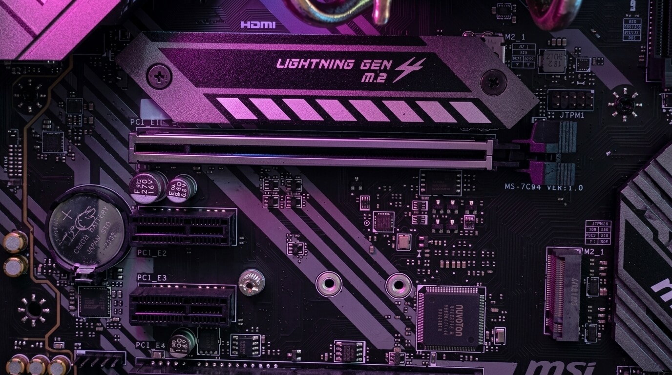
What Are PCIe Slots on a Motherboard?
A PCIe slot is a physical connector on a motherboard that links expansion cards to the computer’s processor and memory through a high-speed serial interface. Motherboards use PCIe slots to connect components such as graphics cards, sound cards, network adapters, storage controllers, and capture cards to the rest of the system.
Each PCIe slot transmits data through one or more communication paths called lanes. A slot with more lanes moves more data per second than a slot with fewer lanes, so slot size and lane count directly affect the performance of the connected component. Motherboard manufacturers place different slot sizes in different positions based on the chipset, the processor, and the intended use of the board.
PCIe slots replaced earlier expansion standards such as PCI and AGP because they provide higher bandwidth, lower latency, and a scalable design that supports multiple slot sizes on the same board. Desktop motherboards typically include a combination of x16, x8, x4, and x1 slots, while laptops and small-form-factor systems use PCIe through M.2 connectors or Mini PCIe slots instead of full-size slots.
This article explains what a PCIe slot is, how PCIe slots differ from PCI slots, the available slot types and generations, how PCIe lanes and bandwidth work, and how to choose the correct slot for a given component.
What Is a PCIe Slot?
A PCIe slot is a motherboard connector that uses the Peripheral Component Interconnect Express (PCIe) standard to link expansion cards directly to the CPU or chipset. The slot carries data across one or more serial lanes, and each lane operates as an independent point-to-point connection between the card and the system.
PCIe slots appear on the motherboard as elongated connectors with a series of contact pins along the base. The physical length of the slot corresponds to its lane count: a longer slot supports more lanes and higher bandwidth than a shorter slot. Manufacturers size the slots as x1, x4, x8, or x16 to match common device requirements, from network cards to graphics cards.
What Does PCIe Stand For?
PCIe stands for Peripheral Component Interconnect Express. The name identifies it as an evolution of the original Peripheral Component Interconnect (PCI) standard, redesigned to use serial data transmission instead of the parallel bus architecture of PCI.
The Peripheral Component Interconnect Special Interest Group (PCI-SIG) develops and maintains the PCIe standard. PCI-SIG defines the electrical specifications, physical slot dimensions, and generational speed increases that motherboard and component manufacturers follow to maintain compatibility across products from different vendors.
What Does a PCIe Slot Look Like on a Motherboard?
A PCIe slot appears as a narrow, elongated connector, usually black, white, or the manufacturer’s accent color, positioned in rows below or beside the CPU socket. The slot has a raised plastic housing with a row of metal contacts along its length and a small locking tab at one end that secures the installed card.
PCIe slots vary in physical length according to lane count. An x1 slot measures approximately 25 millimetres long, while an x16 slot measures approximately 89 millimetres long. Motherboards commonly place one or two long x16 slots near the CPU for graphics cards, with shorter x1 or x4 slots positioned around them for additional expansion cards.
PCIe vs. PCI: What’s the Difference?
PCIe differs from PCI in its data transmission method, bandwidth, and physical slot design. PCI uses a parallel bus architecture shared among all connected devices, while PCIe uses dedicated serial lanes that connect each device directly to the CPU or chipset without sharing bandwidth with other slots.
The shared bus in PCI limits total system throughput because every device on the bus competes for the same fixed bandwidth. PCIe assigns dedicated lanes to each slot, so a device’s performance does not decrease when other PCIe devices are active. PCI supports a maximum theoretical bandwidth of 133 megabytes per second across the entire bus, while a single PCIe 3.0 lane alone supports roughly 985 megabytes per second in each direction.
PCI slots and PCIe slots are not physically or electrically interchangeable. A PCI card cannot fit into a PCIe slot, and a PCIe card cannot fit into a PCI slot, because the connector dimensions, pin layouts, and signaling methods differ between the two standards. Current motherboards no longer include PCI slots; PCIe has replaced PCI as the standard expansion interface since the mid-2000s.
Types of PCIe Slots
PCIe slots come in four common sizes: x1, x4, x8, and x16. Each size corresponds to the number of lanes wired to the slot, and the number appears after the “x” to indicate lane count. A larger slot size provides more bandwidth and physically accommodates smaller cards, but a smaller slot cannot accept a larger card.
Motherboard manufacturers select slot sizes based on the board’s target use. A gaming or workstation motherboard typically includes one or more x16 slots for graphics cards, alongside x1 and x4 slots for expansion cards such as Wi-Fi adapters, sound cards, and capture cards. Server motherboards often include multiple x8 or x16 slots to support storage controllers, network cards, and additional GPUs.
PCIe x1 Slots
A PCIe x1 slot has a single lane and is the shortest and most common PCIe slot on consumer motherboards. It provides the lowest bandwidth of the standard slot sizes, supporting devices that do not require high-speed data transfer.
Manufacturers use x1 slots for components such as Wi-Fi adapters, sound cards, USB expansion cards, and low-bandwidth capture cards. A PCIe 3.0 x1 slot provides approximately 985 megabytes per second of bandwidth in each direction, which exceeds the requirements of most low-throughput peripherals.
PCIe x4 Slots
A PCIe x4 slot has four lanes and provides four times the bandwidth of an x1 slot. Motherboards place x4 slots for components that need moderate throughput, such as some RAID controllers, additional M.2 storage adapters, and 10-gigabit network cards.
A PCIe 3.0 x4 slot delivers approximately 3.94 gigabytes per second in each direction, which supports most NVMe storage controllers and mid-range network adapters without becoming a bottleneck. Some motherboards physically implement an x4 slot with an open-ended design, allowing a longer card to be installed even though only four lanes are wired.
PCIe x8 Slots
A PCIe x8 slot has eight lanes and provides double the bandwidth of an x4 slot. Motherboards use x8 slots less frequently than x1, x4, or x16 slots, and they typically appear on workstation or server boards designed for multiple high-bandwidth expansion cards.
An x8 slot commonly supports high-end RAID controllers, multi-port network cards, and secondary graphics cards in multi-GPU configurations. A PCIe 3.0 x8 slot provides approximately 7.88 gigabytes per second in each direction. Some consumer motherboards physically size a slot as x16 but wire only eight lanes to it, which reduces bandwidth for cards that require the full sixteen lanes.
PCIe x16 Slots
A PCIe x16 slot has sixteen lanes and provides the highest bandwidth among standard PCIe slot sizes. Motherboards reserve x16 slots primarily for graphics cards, which require maximum bandwidth to transfer rendering data between the GPU and the system.
A PCIe 3.0 x16 slot provides approximately 15.75 gigabytes per second in each direction, while a PCIe 4.0 x16 slot doubles that figure to approximately 31.5 gigabytes per second. Most consumer motherboards include one primary x16 slot connected directly to the CPU, with additional x16-sized slots connected through the chipset that may operate at reduced lane counts such as x8 or x4.
PCIe Generations and Versions
PCIe generations define the data transfer speed of each individual lane, with each new generation approximately doubling the bandwidth of the previous one. PCI-SIG has released six generations since the standard’s introduction in 2003: PCIe 1.0, 2.0, 3.0, 4.0, 5.0, and 6.0.
A motherboard’s PCIe generation depends on the CPU and chipset it uses, and different slots on the same board can support different generations. A card of an earlier generation functions correctly in a slot of a later generation, and a card of a later generation functions in a slot of an earlier generation, though the connection operates at the slower generation’s speed in both cases.
PCIe Speed by Generation (1.0–5.0)
PCIe speed per lane increases from 2.5 GT/s in generation 1.0 to 32 GT/s in generation 5.0, approximately doubling with each new generation. The table below lists the raw transfer rate and usable bandwidth per lane, in each direction, for PCIe generations 1.0 through 5.0.
| PCIe Generation | Transfer Rate per Lane | Bandwidth per Lane (each direction) |
|---|---|---|
| 1.0 | 2.5 GT/s | ~250 MB/s |
| 2.0 | 5.0 GT/s | ~500 MB/s |
| 3.0 | 8.0 GT/s | ~985 MB/s |
| 4.0 | 16.0 GT/s | ~1.97 GB/s |
| 5.0 | 32.0 GT/s | ~3.94 GB/s |
The transfer rate, measured in gigatransfers per second (GT/s), reflects the raw signaling speed of a lane. Usable bandwidth is lower than the raw transfer rate because PCIe encodes data with overhead bits for error checking; generations 3.0 and later use a more efficient encoding scheme than generations 1.0 and 2.0, which narrows the gap between raw transfer rate and usable bandwidth.
PCIe Gen 4 vs. Gen 5
PCIe Gen 5 doubles the per-lane bandwidth of PCIe Gen 4, moving from approximately 1.97 gigabytes per second to approximately 3.94 gigabytes per second per lane in each direction. This difference means a Gen 5 x16 slot supports roughly 63 gigabytes per second, compared with approximately 31.5 gigabytes per second for a Gen 4 x16 slot.
Gen 5 requires more precise signal integrity than Gen 4, so motherboards that support Gen 5 typically use higher-quality circuit board materials and shorter trace lengths to maintain a stable connection. Most current consumer GPUs do not yet saturate Gen 4 x16 bandwidth, so the practical performance difference between Gen 4 and Gen 5 remains limited for graphics cards, while high-throughput NVMe SSDs benefit more directly from the added bandwidth of Gen 5.
PCIe Lanes and Bandwidth Explained
PCIe lanes are the individual data paths that carry information between a PCIe slot and the CPU or chipset, and the total number of available lanes determines how many devices a motherboard can support at full speed simultaneously. A processor and chipset each provide a fixed lane budget, and the motherboard divides that budget among the various PCIe slots and onboard components such as M.2 storage.
Bandwidth on a PCIe connection depends on two factors: the number of lanes allocated to a slot and the PCIe generation of both the slot and the connected device. A component connected through more lanes or a newer generation transfers data at a higher rate than the same component connected through fewer lanes or an older generation.
What Are PCIe Lanes?
A PCIe lane is a single serial data path consisting of two wire pairs, one for transmitting data and one for receiving data simultaneously. Each lane operates independently, so a slot with multiple lanes transfers data across all of them in parallel to increase total throughput.
A CPU and chipset each expose a limited number of physical lanes, and the motherboard routes these lanes to the various PCIe slots, M.2 slots, and onboard controllers. Consumer desktop CPUs commonly provide between 20 and 28 usable PCIe lanes, while high-end desktop and server processors provide substantially more, which allows those platforms to run multiple x16 or x8 slots at full bandwidth at the same time.
How Many PCIe Lanes Does a GPU Use?
A GPU typically uses 16 PCIe lanes when installed in a full x16 slot, which provides the maximum bandwidth available to a single graphics card on a consumer motherboard. Some motherboards or multi-GPU configurations reduce this allocation to eight lanes when lanes are shared among multiple slots.
Modern GPUs rarely require the full bandwidth of a PCIe 3.0 or PCIe 4.0 x16 connection during typical gaming workloads, so running a GPU at x8 instead of x16 produces a measurable but often small performance difference on current-generation cards. The performance impact of reduced lane count grows more noticeable on older PCIe generations, where the available bandwidth per lane is lower.
PCIe Bandwidth by Lane Count and Generation
PCIe bandwidth scales directly with both lane count and generation, so a slot’s total bandwidth equals the per-lane bandwidth of its generation multiplied by its lane count. The table below shows approximate bandwidth, in each direction, across common lane counts and generations.
| Lanes | Gen 3.0 | Gen 4.0 | Gen 5.0 |
|---|---|---|---|
| x1 | ~0.99 GB/s | ~1.97 GB/s | ~3.94 GB/s |
| x4 | ~3.94 GB/s | ~7.88 GB/s | ~15.75 GB/s |
| x8 | ~7.88 GB/s | ~15.75 GB/s | ~31.5 GB/s |
| x16 | ~15.75 GB/s | ~31.5 GB/s | ~63.0 GB/s |
This scaling relationship explains why a PCIe 4.0 x8 slot provides the same bandwidth as a PCIe 3.0 x16 slot: doubling the per-lane speed offsets halving the lane count. Component manufacturers use this relationship to design cards, such as some NVMe storage adapters, that achieve high bandwidth through fewer lanes on newer PCIe generations.
What Can You Plug Into a PCIe Slot?
A PCIe slot accepts any expansion card built to the PCIe standard, provided the card’s physical size does not exceed the slot’s length. Common devices installed in PCIe slots include graphics cards, sound cards, Wi-Fi and Bluetooth adapters, wired network cards, RAID and storage controllers, USB expansion cards, capture cards, and TV tuner cards.
Graphics cards require an x16 slot to access sufficient bandwidth for rendering tasks, while lower-bandwidth devices such as sound cards and Wi-Fi adapters typically use x1 slots. Storage expansion cards that add M.2 NVMe drives to a motherboard commonly use x4 or x16 slots, depending on how many drives the card supports. A smaller card, such as an x1 or x4 card, installs and functions correctly in a larger slot, such as an x8 or x16 slot, because PCIe slots maintain backward physical and electrical compatibility with smaller card sizes.
How to Choose the Right PCIe Slot for Your Component
Choosing the right PCIe slot requires matching the component’s bandwidth requirements and physical size to an available slot with sufficient lanes and generation support. A graphics card needs the primary x16 slot connected directly to the CPU, while lower-bandwidth components such as network cards or sound cards fit appropriately in x1 or x4 slots without a measurable performance loss.
Checking the motherboard manual clarifies which slots connect directly to the CPU and which connect through the chipset, since chipset-connected slots share bandwidth with other onboard components such as SATA ports and additional M.2 slots. Installing a high-bandwidth device, such as a second GPU or a high-speed storage controller, in a chipset-connected slot can reduce available bandwidth for other components sharing that same chipset link.
Does It Matter Which PCIe Slot You Use for a GPU?
Yes, it matters which PCIe slot is used for a GPU, because only the primary x16 slot connected directly to the CPU provides full bandwidth and, on many boards, direct display output support. Installing a GPU in a secondary slot connected through the chipset can reduce available bandwidth and, on some motherboards, disable certain onboard features.
Motherboard manuals typically label the CPU-connected slot as the first or topmost x16 slot, positioned closest to the CPU socket. Secondary x16-sized slots often operate at reduced lane counts, such as x4 or x8, and route through the chipset rather than directly through the CPU, which introduces additional latency and reduces peak bandwidth compared with the primary slot.
How Many PCIe Slots Do I Need?
The number of PCIe slots needed depends on the number of expansion cards planned for the system, including the graphics card and any additional storage, networking, or audio cards. A typical single-GPU gaming build requires one x16 slot for the graphics card and, optionally, one or two smaller slots for peripherals such as a Wi-Fi adapter or capture card.
Builds that include multiple GPUs, dedicated RAID controllers, or several expansion cards require a motherboard with additional x16, x8, or x4 slots, along with a CPU and chipset that provide enough total PCIe lanes to support them without reducing bandwidth below acceptable levels. Confirming the total lane count of the target CPU and chipset before selecting a motherboard prevents a shortage of usable bandwidth when multiple slots operate simultaneously.
PCIe Compatibility and Common Limitations
PCIe maintains compatibility across slot sizes and generations, but shared bandwidth and lane allocation limits create practical constraints on how many devices a motherboard can run at full speed at once. Understanding these limitations helps prevent unexpected bandwidth reductions when installing multiple PCIe devices on the same board.
Common limitations include fixed lane budgets from the CPU and chipset, bandwidth sharing between certain slots and M.2 connectors, and reduced performance when a device operates in a slot with fewer lanes than the device supports.
Is PCIe Backward and Forward Compatible?
Yes, PCIe is both backward and forward compatible across generations and slot sizes, so a card from any PCIe generation functions in a slot of a different generation, and a smaller card functions in a larger slot. The connection between a card and a slot from different generations operates at the speed of the older generation of the two.
A physically smaller card, such as an x1 card, installs and operates correctly in a larger slot, such as an x16 slot, using only the lanes it requires. A physically larger card cannot fit into a smaller slot unless the slot uses an open-ended design that allows extra pins to remain unconnected, in which case the card operates at the slot’s lower lane count rather than its full lane count.
PCIe Bifurcation and Shared Bandwidth (e.g., M.2 Slots Reducing x16 Bandwidth)
PCIe bifurcation is the process of splitting a single PCIe slot’s lanes into multiple smaller connections, allowing one physical slot to serve more than one device simultaneously. Motherboard manufacturers implement bifurcation to support configurations such as adapter cards that host multiple M.2 NVMe drives in a single x16 slot.
Some motherboards reduce the lane count of the primary x16 slot when an M.2 slot is populated, because both connections share a limited pool of lanes from the CPU or chipset. For example, installing a drive in a specific M.2 slot on some boards reduces the primary graphics slot from x16 to x8, which lowers available GPU bandwidth. Checking the motherboard manual’s lane-sharing diagram before installing additional M.2 drives or bifurcated adapter cards prevents an unexpected reduction in GPU or other device bandwidth.
PCIe Slots on Laptops and Small-Form-Factor PCs
Laptops and small-form-factor PCs generally do not include full-size PCIe slots because of space constraints, and instead implement PCIe connectivity through smaller form factors such as M.2 slots and, in older systems, Mini PCIe slots. These compact connectors carry the same underlying PCIe lanes and generational speeds as full-size slots but use a smaller physical footprint suited to thin or compact chassis designs.
M.2 slots in laptops commonly connect NVMe solid-state drives and wireless network cards using one, two, or four PCIe lanes, depending on the slot’s configuration. A small number of small-form-factor desktop systems and some gaming laptops support external GPU enclosures that connect through Thunderbolt, which itself carries PCIe data over a compact external port to provide graphics card connectivity without an internal full-size x16 slot.
PCIe vs. M.2: Which Should You Use?
The choice between PCIe and M.2 depends on the component being installed: M.2 suits compact storage and wireless devices, while a full-size PCIe slot suits larger cards such as graphics cards and multi-port controllers that require higher lane counts or physical space for cooling and connectors. Both interfaces use the same underlying PCIe lanes and generational speeds, so the decision centers on the physical form factor and lane requirements of the device rather than on differences in the PCIe protocol itself.
An M.2 NVMe SSD typically uses up to four PCIe lanes and fits directly onto the motherboard without a separate expansion card, which saves space and simplifies cable routing compared with a PCIe storage adapter card. A graphics card, network controller with multiple ports, or RAID card generally requires a full-size PCIe slot because these devices need more lanes, additional physical space, or external connectors that an M.2 form factor cannot accommodate. Selecting M.2 for compact, lane-limited components and reserving full-size PCIe slots for higher-bandwidth or physically larger devices makes efficient use of a motherboard’s available lanes and slot space.
High-performance gaming PCs built for gamers, creators, and competitors.
More From The Journal
Motherboard: Definition, Function, Sizes, Components
Learn what a motherboard is, what it does, how form factors differ, and which core parts like sockets, chipsets, VRMs, slots, ports, and headers matter most.
How to Choose a Motherboard: A Complete Buying Guide
Learn how to choose a motherboard by comparing socket compatibility, chipset features, RAM support, PCIe slots, storage options, rear I/O, and power delivery.